4 leg Potentiometer


(Left) Potentiometer 100K
Log ALPS Audio Amp Volume Control
Potentiometer Tapers
The taper (also called 'law') of a pot is important. We need not
worry with trimpots, since they are almost always
linear, and I do not know of a supplier of anything other than linear trimpots. For all panel pots, we must be aware of the use
the pot will have, and select the correct type accordingly.
The most common use of a pot in audio is for a volume control.
Since our hearing has a logarithmic response to sound pressure, it is important
that the volume control should provide a smooth variation from soft to loud,
such that a given change in position of the pot causes the same sensation of
volume change at all levels.

Pot
Markings
Now, this should be dead easy - a simple code to
indicate the resistance and law of a pot should cause no grief to anyone,
right? Wrong! It wouldn't have been so bad if someone hadn't decided to change
it, and even then, it wouldn't have been so bad if there was no overlap between
the 'old' and 'new' 'standards' ... I think you can see where this is headed by
now.
|
Taper |
Old Code |
New Code |
Alternate |
|
Linear |
A |
B |
LIN |
|
Log (Audio) |
C |
A |
LOG |
|
Antilog |
F |
N/A |
N/A |
For detail, take a look
here à Introduction to potentiometer
Better Volume (and Balance) Controls à see this article
An
old audio amplifier what has a bad volume control potentiometer.
Bad thing is that it is an old ALPS potentiometer 4 pin (3+
center tap for loudness control).
It is impossible to find a replacement. If i use normal 3
pin potentiometers i can not use the loudless controls.
It is a 100K potentiometer taped at 50% Here is a picture fo what it looks like.
If i use 50K external resistors to make the 4th pin will it work
?

A loudness control works by changing the
frequency response of the amplifier to compensate for frequency response
changes in human hearing at low volume levels. Patents go back to 1939.
Loudness compensation wiki
Audio loudness control original from here
If your main amplifiers. But the sound is not
clear as low treble and little bass. We offer an easy way. Using
less equipment. You create a very simple
Audio loudness control
circuit used to add bass. More during the normal listening
levels. It is a
passive circuit and does not use the power supply.

When
the input signal into. Switch S1
is an option to use open (ON) using loudness control. Off (OFF) to use a
bypass. When the switch S1 to the ON position the signal will flow through C1(0.001uF), C2(0.01uF) and R1(2K). This will serve as a low
pass filter circuit.VR1 is adjusted by the strength of the signal to the
output.VR1-100K Linear Potentiometer, which uses the volume type with a central
bar (Center Tap) only. The output of the circuit will be connected to the
region to pre-tone next step.
Note: All capacitors use
Ceramic Capacitor or Mylar Capacitor them low cost
How to build
This circuit has a few components so you can builds
easily as Figure 2 make PCB layout and putting all components on PCB and
connecting to your audio system.
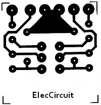
Figure 2 The
PCB and components layout of this projects.
Most pot 'gangs'
are 3 terminal types, but there are some with a tapping partway along the
resistance element. This was used in the bad old days to create a 'loudness'
control, where the bass and treble are increased at low levels to compensate
for the way our hearing reacts to different levels. Because there was rarely
(if ever) any attempt to match the acoustic power levels, the loudness control
was always wrong. To get it right requires source, preamp, power amp and
speakers to have a known gain/ sensitivity, and ideally a preset control would
have been incorporated to ensure the system could be calibrated. This was never
done by the vast majority of manufacturers - Yamaha appears to be the only
maker who even made an attempt (I don't know how good it was, never having seen
a system that used it).

Note the RC filters above and below the centre-tap. This circuit does seem to have a trimmer so it
might be a little better than Elliot's description.
In the '70s and '80s many amplifiers had a
"loudness" switch to create the same effect. I still have one on an
old JVC amplifier. The datasheet example attempts to automate it.

Figure
1. Equal-loudness curves. Source: Fletcher-Munson
curves on Wikipedia.
There is an excellent
article, The Mysterious Loudness Control:
What Does It Do? by Steve Somers, Vice
President of Engineering at Extron. He gives
background to the Fletcher-Munson equal loudness contours developed at Bell
Labs in the 1930s, covers basic circuits and mentions DSP.
It
is a pot with a (probably center) tap. They used to be more-or-less common in
audio design, typically in the 'tone control' circuit.
See,
for example, this guitar
amplifier schematic:
